Understanding PLC Programming Basics Guide in Industrial Automation Solution
Which programming language is most commonly used for PLCs?

PLC Programming Basics: A Practical Guide for Industrial Automation
Programmable Logic Controllers (PLCs) are at the heart of modern industrial automation. From controlling conveyor systems in manufacturing plants to managing complex chemical processes, PLCs ensure that machines operate reliably, safely, and efficiently.
Understanding PLC programming basics is one of the most important skills for automation engineers, technicians, and anyone working in industrial control systems. At its core, PLC programming involves writing instructions that allow machines and processes to respond automatically to real-world conditions such as sensor inputs, timing requirements, and operator commands.
This article provides a detailed introduction to PLC programming fundamentals. You’ll learn how PLCs work, the most common programming languages used in automation, and the key concepts every beginner should understand before writing their first control program.
Understanding PLC Programming
PLC programming refers to the process of creating logic instructions that tell a PLC how to control machines, sensors, and industrial equipment. These instructions determine how the system reacts to various input signals and what actions should be taken.
PLCs were originally developed to replace complex relay-based control panels. Instead of wiring hundreds of electrical relays together, engineers could program the same control logic using software. This dramatically simplified machine control and made systems easier to modify and maintain.
Today, PLCs are used in industries such as: Manufacturing, Oil and gas, Food processing, Power generation, Water treatment, Automotive production
PLC programming allows these industries to automate repetitive tasks, improve safety, and ensure consistent production quality.
How PLC Programs Control Industrial Systems
At a fundamental level, a PLC program monitors inputs, processes logic conditions, and controls outputs.
A simplified PLC operation cycle typically follows this sequence:
The PLC reads signals from input devices such as sensors and switches.
The program evaluates the input conditions based on programmed logic.
The PLC updates the outputs, controlling devices like motors, valves, and lights.
The cycle repeats continuously.
This repeating loop is called the PLC scan cycle, allowing the controller to respond to changes in the system almost instantly.
Key Components of a PLC System
Before writing PLC programs, it is important to understand the hardware components involved.
PLC CPU (Central Processing Unit)
The CPU is the brain of the PLC system. It executes the control program and processes input data to determine output actions.
The CPU performs several tasks:
Reading input signals
Executing the control program
Updating output devices
Managing communication with other systems
Modern PLC CPUs are designed to operate reliably in harsh industrial environments, including high temperatures, electrical noise, and vibration.
Input Devices
Inputs provide the PLC with information about the state of the system.
Common input devices include: Push buttons, Limit switches, Proximity sensors, Temperature sensors, Pressure transmitters
Inputs can be either digital (on/off) or analog (variable signals such as temperature or pressure).
The PLC reads these signals and uses them to determine how the system should respond.
Output Devices
Outputs allow the PLC to control physical equipment.
Examples include: Electric motors, Solenoid valves, Pumps, Indicator lights, Relays.
When the program conditions are satisfied, the PLC activates the output device to perform the required action.
Input and Output Modules
Input and output modules act as the interface between the PLC and field devices.
Input modules convert electrical signals from sensors into data the PLC can process. Output modules convert PLC signals into electrical signals that operate machines and equipment.
PLC Programming Languages
PLC programming follows standardized languages defined in the IEC 61131-3 industrial automation standard. Each language offers different advantages depending on the complexity of the control system.
Ladder Logic (LD)
Ladder Logic is the most widely used PLC programming language.
It uses a graphical format that resembles electrical relay diagrams. Vertical lines called rails represent the power supply, while horizontal lines called rungs represent the logic instructions.
Each rung defines the conditions required to activate an output device.
Because ladder diagrams visually resemble traditional relay circuits, they are easy for electricians and technicians to understand.
This simplicity makes ladder logic the preferred programming language for many industrial automation systems.
Basic Ladder Logic Elements
Several fundamental elements make up ladder logic programs.
Contacts
Contacts represent input conditions. They evaluate whether a device is on or off.
Coils
Coils represent outputs such as motors or relays.
Rungs
Each rung represents a control instruction within the ladder program.
Branches
Branches allow multiple logic conditions to operate in parallel.
These elements combine to create complex control logic for automated systems.
Function Block Diagram (FBD)
Function Block Diagram is another graphical programming language used in PLC systems.
Instead of ladder rungs, it uses blocks that represent specific functions such as:
mathematical calculations
signal processing
logic operations
Each block has inputs and outputs that can be connected to other blocks.
FBD is particularly useful for complex control systems involving advanced calculations or analog processing.
Structured Text (ST)
Structured Text is a text-based programming language similar to traditional programming languages such as Pascal or C.
It uses statements like:
IF temperature > 80 THEN
   fan := TRUE;
END_IF;
Structured Text is commonly used in advanced control applications that require complex calculations or data manipulation.
Fundamental PLC Programming Concepts
To write effective PLC programs, engineers must understand several key programming concepts.
Digital Logic
PLC programs rely heavily on basic digital logic operations.
The three most common logic functions are:
AND Logic
The output activates only when all input conditions are true.
OR Logic
The output activates if any input condition is true.
NOT Logic
The output activates when the input condition is false.
By combining these logic operations, engineers can create complex control sequences.
Timers
Timers allow PLC programs to control time-based events.
Timers can be used to:
delay machine startup
control production cycle timing
turn outputs on or off after a specified duration
Timers are widely used in industrial processes such as packaging systems or automated assembly lines.
Counters
Counters track how many times an event occurs.
For example, counters may be used to:
count the number of products on a conveyor
monitor machine cycles
trigger maintenance alerts after a certain number of operations
Counters are essential for production monitoring and automation control.
Interlocks and Safety Logic
Safety interlocks ensure that machines operate only under safe conditions.
For example, a motor might only start when:
a safety guard is closed
an emergency stop is reset
another machine is not running
These safety conditions are built directly into PLC programs to prevent equipment damage or operator injury.
Example of a Simple PLC Program
A basic PLC control program might operate a conveyor motor.
Control conditions:
The conveyor starts when the start button is pressed.
The conveyor stops when the stop button is pressed.
The ladder logic would include: Start button input, Stop button input, Motor output coil.
If the start condition becomes true and the stop condition remains false, the motor output is energized.
Even simple programs like this demonstrate how PLCs automate industrial processes.
Best Practices for PLC Programming
Writing reliable PLC programs requires careful planning and structured design.
Experienced automation engineers typically follow several best practices.
Use Clear Tag Names
Instead of using memory addresses like I:0/1, use descriptive names such as:
Start_Button
Motor_Run
Emergency_Stop
Clear tag names make programs easier to understand and maintain.
Organize Programs into Logical Sections
Large PLC programs should be divided into logical sections such as:
startup logic
safety systems
machine control
alarms and diagnostics
This improves readability and simplifies troubleshooting.
Add Comments and Documentation
Comments explain the purpose of each program section.
For example:
Motor control logic for conveyor system
Proper documentation helps future engineers understand how the system works.
Test Programs Carefully
Before deploying PLC programs in production systems, engineers should test them using simulation tools or test equipment.
Testing helps identify logic errors before they affect production equipment.
Applications of PLC Programming
PLC programming is used in a wide range of industries and automation applications.
Manufacturing Automation
In manufacturing plants, PLC programs control:
assembly lines
robotic systems
packaging equipment
conveyor systems
These systems enable high-speed, reliable production.
Process Control
Industries such as chemical processing and oil refining rely on PLC programs to monitor and control: temperature, pressure, flow rates, chemical reactions.
Automation helps maintain safe operating conditions.
Building Automation
PLCs are also used in building management systems to control:
HVAC systems
lighting systems
energy management
This improves energy efficiency and operational reliability.
- Industrial Automation Fundamentals
- Industrial Communication Protocols
- Industrial Instrumentation Control
- Industrial Sensors & Measurement
- Motion and Process Control
- PLC Programming & Controllers
- SCADA and DCS Systems
- Servo Motors and Motor Drives
Frequently Asked Questions (FAQ)
What is PLC programming?
PLC programming is the process of creating logic instructions that allow programmable logic controllers to monitor inputs and control industrial machines and processes automatically.
Which programming language is most commonly used for PLCs?
Ladder Logic is the most widely used PLC programming language because its graphical structure resembles electrical relay circuits, making it easier for technicians and engineers to understand.
What industries use PLC programming?
PLC programming is widely used in manufacturing, oil and gas, power generation, water treatment, food processing, and many other industries.
How long does it take to learn PLC programming?
Many beginners can understand the basics of PLC programming in a few months, but mastering industrial automation programming can take years of practical experience.
What skills are required to become a PLC programmer?
Important skills include:
electrical control systems knowledge
industrial automation fundamentals
ladder logic programming
troubleshooting skills
understanding of sensors and industrial networks
Your One-Stop Source for Reliable Automation & Process Control Equipment
Access trusted process control equipment, expert support, and fast sourcing—all in one place.
-
AC Drives 18,165 Products
-
Butterfly Valve236 Products
-
Circuit Breakers2,226 Products
-
Contactors567 Products
-
Counters78 Products
-
Encoder117 Products
-
Fanuc Main Board1,376 Products
-
Flow Transmitter (Flow meter)552 Products
-
HMI/Touch Screen592 Products
-
Inverter911 Products
-
Network/Signal4 Products
-
Others4,613 Products
-
Power Supply218 Products
-
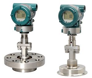
Pressure Transmitter146 Products
-
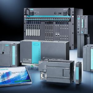
Programmable Logic Controller (PLC)6,290 Products
-
Relay927 Products
-
Sensor2,221 Products
-
Servo Motors & Motor Drives4,499 Products
-
Switch897 Products
-
Timer93 Products
-
Uncategorized1,143 Products
-
Valve Controller & Manifolds15 Products
-
Variable Frequency Drives (VFD)257 Products
-
Yokogawa Remote Indicators16 Products