Understanding CAN Bus Protocol and How It Works
Understanding CAN Bus Protocol and How it Works in Factory Automation Control
How does CAN bus work? and What is the difference between CAN and CAN FD?
Understanding CAN Bus Protocol and How It Works
In modern industrial systems and vehicles, reliable communication between electronic devices is non-negotiable. As machines become more interconnected, the need for fast, deterministic, and fault-tolerant communication protocols has only grown. One protocol that has stood the test of time is the Controller Area Network (CAN) bus.
Originally developed for automotive applications, CAN bus has evolved into a widely adopted communication standard across industrial automation, medical devices, and embedded systems. Its simplicity, robustness, and real-time capabilities make it a foundational technology in both legacy systems and modern Industry 4.0 environments.
This guide breaks down what CAN bus is, how it works, and why it remains a critical communication protocol in industrial automation.
What Is CAN Bus Protocol?
The Controller Area Network (CAN) bus is a serial communication protocol designed to allow multiple electronic devices—often called nodes—to communicate with each other without the need for a central host computer.
Unlike traditional communication systems that rely on point-to-point wiring, CAN bus uses a multi-master, message-based architecture. This means every device on the network can send and receive messages, and communication is prioritized based on message importance rather than device hierarchy.
CAN bus was initially developed by Bosch in the 1980s for automotive applications, where reducing wiring complexity and improving reliability were critical. Today, it is used far beyond vehicles, including in factory automation systems, robotics, and industrial control networks.
At its core, CAN bus is designed to provide:
- High reliability in noisy environments
- Real-time communication capabilities
- Efficient data exchange between devices
- Fault detection and error handling mechanisms
Why CAN Bus Is Important in Industrial Automation
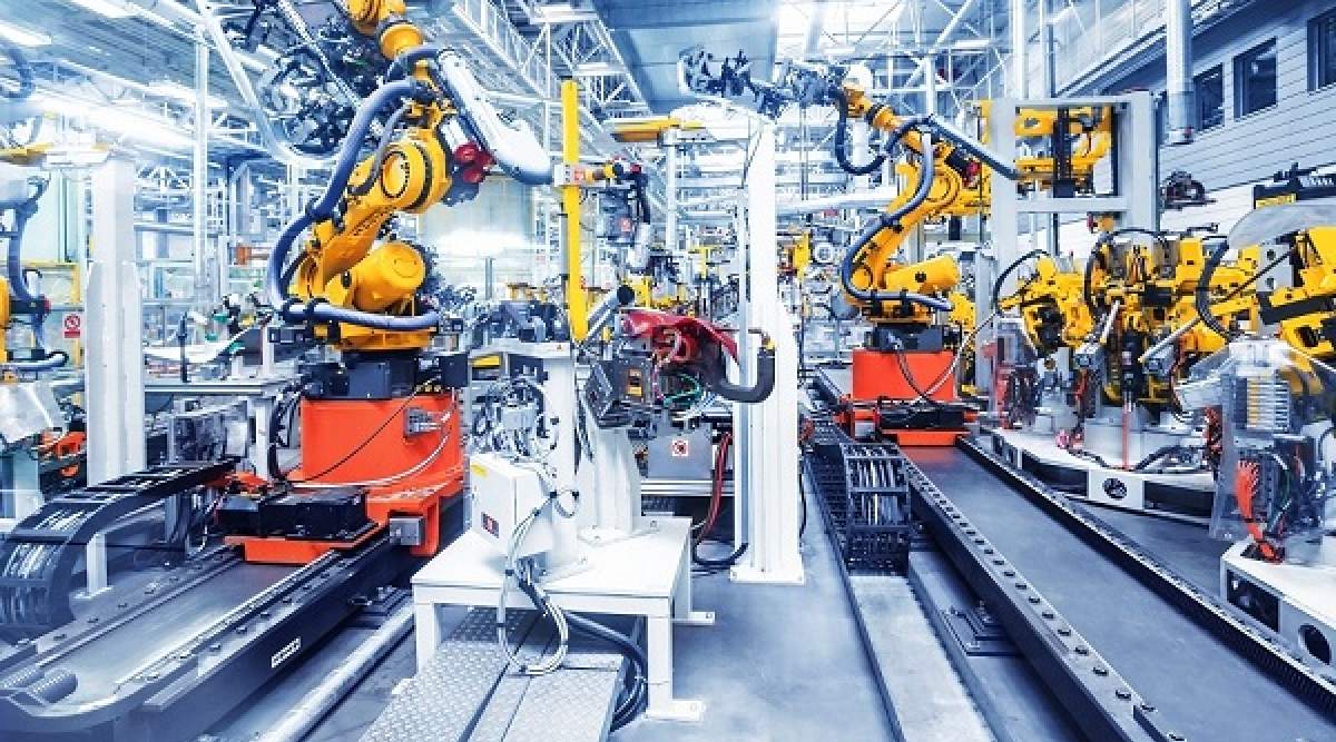
Industrial environments are often electrically noisy and require systems that can maintain communication integrity under challenging conditions. CAN bus is particularly well-suited for these environments due to its robust design. In industrial automation, CAN bus is commonly used for:
- Machine-to-machine communication
- Sensor and actuator integration
- Distributed control systems
- Robotics and motion control
Its ability to function without a central controller makes it ideal for decentralized systems where multiple devices must communicate independently. Another key advantage is reduced wiring. Instead of running individual cables between every device, CAN bus uses a shared communication line, significantly simplifying system design and installation.
How CAN Bus Works
To understand how CAN bus operates, it helps to look at its communication model and the way data is transmitted across the network.
CAN Bus Network Structure
A CAN network consists of multiple nodes connected to a common communication medium known as the bus. Each node typically includes:
- A microcontroller
- A CAN controller
- A CAN transceiver
All nodes are connected to two wires:
- CAN High (CAN_H)
- CAN Low (CAN_L)
These wires form a differential signaling system, which improves noise immunity and ensures reliable communication even in harsh environments.
Message-Based Communication
Unlike traditional address-based communication systems, CAN bus uses a message-based protocol. This means:
- Messages are broadcast to all nodes
- Each message contains an identifier
- Nodes decide whether to process the message based on the identifier
This approach allows for efficient data sharing and reduces communication overhead. For example, a temperature sensor can broadcast data to the entire network, and only the relevant controllers will process that information.
Arbitration and Priority
One of the most important features of CAN bus is its arbitration mechanism, which ensures that multiple devices can communicate without data collisions. When multiple nodes attempt to transmit simultaneously:
- Messages are assigned priority based on their identifier
- Lower numerical identifiers have higher priority
- The highest-priority message continues transmission
- Other nodes wait and retry
This process is known as non-destructive arbitration, meaning no data is lost during contention.
Data Frames in CAN Bus
Communication in CAN bus is organized into structured units called frames. The main types of CAN frames include:
- Data Frame – used to transmit actual data
- Remote Frame – requests data from another node
- Error Frame – indicates a communication error
- Overload Frame – used to manage network timing
A standard data frame includes:
- Identifier (message priority)
- Control field
- Data field (up to 8 bytes in classic CAN)
- CRC (error checking)
- Acknowledgment field
This structured format ensures reliable and predictable communication.
Error Detection and Fault Handling
CAN bus includes built-in error detection mechanisms that make it highly reliable. These include:
- Cyclic Redundancy Check (CRC)
- Bit monitoring
- Frame checks
- Acknowledgment checks
If a node detects an error, it immediately transmits an error frame, prompting all nodes to discard the corrupted message. Faulty nodes can also be automatically isolated from the network, preventing system-wide failures.
Key Components of a CAN Bus System
Understanding the components involved helps clarify how CAN bus systems are implemented in real-world applications.
CAN Controller
The CAN controller manages communication logic, including message framing, arbitration, and error detection. It acts as the interface between the microcontroller and the CAN network.
CAN Transceiver
The transceiver converts digital signals from the controller into differential signals for transmission over the CAN bus. It also receives signals from the bus and converts them back into digital form.
Nodes (Devices)
Each device on the network is referred to as a node. Examples include:
- Sensors
- Actuators
- PLCs
- Motor controllers
- Embedded systems
Every node can send and receive messages independently.
Communication Medium
The CAN bus itself consists of a twisted pair of wires (CAN_H and CAN_L) designed to reduce electromagnetic interference. Proper termination resistors are required at both ends of the bus to prevent signal reflections.
Types of CAN Bus Protocols
Over time, several variations of CAN have been developed to meet different performance requirements.
Classical CAN
Classical CAN is the original version of the protocol. It supports:
- Data rates up to 1 Mbps
- Maximum payload of 8 bytes per frame
It is still widely used in automotive and industrial systems.
CAN FD (Flexible Data Rate)
CAN FD is an enhanced version of classical CAN. It offers:
- Higher data rates (up to 8 Mbps or more)
- Larger data payloads (up to 64 bytes)
CAN FD is ideal for applications requiring faster data transfer and higher bandwidth.
CANopen Protocol
CANopen is a higher-layer protocol built on top of CAN. It standardizes communication between devices, making integration easier in industrial systems. CANopen is commonly used in:
- Factory automation
- Medical equipment
- Motion control systems
DeviceNet
DeviceNet is another protocol built on CAN, primarily used in industrial automation. It provides a standardized way to connect industrial devices such as sensors and actuators.
Advantages of CAN Bus
CAN bus offers several advantages that explain its widespread adoption.
High Reliability
Its error detection and fault-handling capabilities ensure robust communication even in noisy environments.
Real-Time Communication
The priority-based arbitration system ensures that critical messages are transmitted without delay.
Reduced Wiring Complexity
A single bus replaces complex point-to-point wiring, simplifying system design.
Scalability
New devices can be added to the network without major system changes.
Cost-Effective Implementation
Lower wiring requirements and standardized components reduce overall system costs.
Limitations of CAN Bus
Despite its strengths, CAN bus has some limitations.
Limited Data Payload
Classical CAN supports only 8 bytes per message, which can be restrictive for data-intensive applications.
Bandwidth Constraints
Compared to modern industrial Ethernet protocols, CAN bus has lower data transfer rates.
Network Size Limitations
The number of nodes and network length are limited by signal timing and electrical characteristics.
Applications of CAN Bus
CAN bus is used across a wide range of industries.
Automotive Systems
CAN bus is the backbone of modern vehicles, connecting:
- Engine control units
- Transmission systems
- ABS and braking systems
- Infotainment systems
Industrial Automation
In factories, CAN bus connects sensors, actuators, and controllers to enable efficient machine communication.
Medical Equipment
Medical devices use CAN bus for reliable and real-time communication.
Robotics and Embedded Systems
Robotic systems rely on CAN bus for motion control and coordination between components.
Recommended Related Articles:
https://www.automationpioneer.com/plc-programming-basics
PLC Programming Basics
https://www.automationpioneer.com/what-is-scada-system
What Is SCADA System
https://www.automationpioneer.com/plc-vs-dcs
PLC vs DCS Explained
https://www.automationpioneer.com/types-of-industrial-sensors
Types of Industrial Sensors
https://www.automationpioneer.com/industrial-communication-protocols
Industrial PLC Communication Protocols Guide
https://www.automationpioneer.com/pressure-transmitters-guide
Pressure Transmitter Guide
https://www.automationpioneer.com/industrial-iot-guide
Industrial IoT Guide
Frequently Asked Questions (FAQ)
What is CAN bus in simple terms?
CAN bus is a communication system that allows multiple electronic devices to communicate with each other over a shared network without a central controller.
How does CAN bus work?
CAN bus works by broadcasting messages across a shared network. Each message includes an identifier, and devices decide whether to process the message based on that identifier.
What is the difference between CAN and CAN FD?
CAN FD supports higher data rates and larger data payloads compared to classical CAN, making it more suitable for modern high-speed applications.
Where is CAN bus used?
CAN bus is used in automotive systems, industrial automation, robotics, medical devices, and embedded systems.
Why is CAN bus reliable?
CAN bus includes built-in error detection, fault isolation, and priority-based communication, ensuring reliable operation even in harsh environments.
Your One-Stop Source for Reliable Automation & Process Control Equipment
Access trusted process control equipment, expert support, and fast sourcing—all in one place.
-
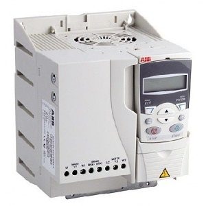
AC Drives 18,160 Products
-
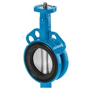
Butterfly Valve236 Products
-
Circuit Breakers2,226 Products
-
Contactors567 Products
-
Counters78 Products
-
Encoder117 Products
-
Fanuc Main Board1,376 Products
-
Flow Transmitter (Flow meter)396 Products
-
HMI/Touch Screen592 Products
-
Inverter911 Products
-
Network/Signal4 Products
-
Others4,668 Products
-
Power Supply218 Products
-
Pressure Transmitter143 Products
-
Programmable Logic Controller (PLC)6,288 Products
-
Relay927 Products
-
Sensor2,221 Products
-
Servo Motors & Motor Drives4,363 Products
-
Switch897 Products
-
Timer93 Products
-
Uncategorized1,145 Products
-
Valve Controller & Manifolds15 Products
-
Variable Frequency Drives (VFD)258 Products
-
Yokogawa Remote Indicators16 Products