
How to Calibrate Pressure Transmitters

How to Calibrate Pressure Transmitters: A Practical Step-by-Step Guide for Engineers
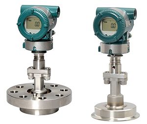
Pressure transmitters are among the most critical instruments in industrial automation. Whether you’re working in oil and gas, power generation, or manufacturing, accurate pressure measurement is essential for process control, safety, and product quality.
But here’s the reality—pressure transmitters drift over time. Environmental conditions, mechanical stress, and sensor aging all contribute to measurement inaccuracies. Calibration is what brings these instruments back to accuracy.
This guide walks through how to calibrate pressure transmitters properly, based on real-world industrial practices—not just textbook theory.
Understanding Pressure Transmitter Calibration
Calibration is the process of comparing a transmitter’s output against a known reference standard and adjusting it to eliminate error.
In most industrial systems, pressure transmitters output a 4–20 mA signal, where:
- 4 mA = 0% pressure (Lower Range Value – LRV)
- 20 mA = 100% pressure (Upper Range Value – URV)
The goal of calibration is to ensure that the transmitter output matches the actual applied pressure across the full range.
Over time, transmitters can lose accuracy due to component drift. Calibration restores measurement reliability and ensures the process operates within safe limits.
Why Calibration Is Critical in Industrial Systems
Calibration is not just a maintenance task—it directly impacts operations.
- Prevents process deviations and product quality issues
- Ensures safety in high-pressure systems
- Reduces downtime and equipment failure
- Maintains compliance with industry standards
Even small measurement errors can lead to significant operational problems, especially in continuous processes.
Types of Pressure Transmitter Calibration
Calibration can be performed in different ways depending on operational requirements.
Bench Calibration
Bench calibration is performed in a controlled environment, typically in a workshop or laboratory.
- Higher accuracy due to stable conditions
- Easier troubleshooting
- Ideal for commissioning and detailed testing
This method allows technicians to use high-precision instruments and eliminate environmental variables.
Field Calibration
Field calibration is done directly in the plant without removing the transmitter.
- Faster and less disruptive
- Suitable for routine checks
- Limited accuracy compared to bench calibration
Field calibration is often used for verification rather than full adjustment.
Equipment Required for Calibration
Before starting calibration, ensure you have the correct tools.
Essential Calibration Tools
A proper setup typically includes:
- Pressure calibrator (pneumatic or hydraulic)
- Digital multimeter or loop calibrator
- 24V DC power supply
- HART communicator (for smart transmitters)
- Test hoses and fittings
The reference instrument must be significantly more accurate than the transmitter being calibrated to ensure reliable results.
Safety Considerations
Before calibration begins:
- Isolate the transmitter from the process
- Depressurize the system completely
- Use proper PPE
- Follow plant safety procedures
Proper isolation and depressurization are critical to avoid damage or injury.
Step-by-Step Pressure Transmitter Calibration Procedure
This is where most engineers make mistakes—not in understanding theory, but in execution.
Below is a practical, field-proven calibration workflow.
Step 1: Isolate and Prepare the Transmitter
Start by removing the transmitter from active process conditions.
- Close isolation valves
- Open vent valves to release pressure
- Ensure no trapped pressure remains
Proper isolation ensures safe and accurate calibration.
Step 2: Connect Calibration Equipment
Set up your calibration loop:
- Connect pressure calibrator to the transmitter input
- Connect multimeter in series to measure 4–20 mA output
- Apply power supply to transmitter
- Connect HART communicator if applicable
Ensure all connections are leak-free and secure.
Step 3: Perform As-Found Check
Before making any adjustments, record current performance. Apply pressure at:
- 0%
- 25%
- 50%
- 75%
- 100%
Compare measured output with expected values. Example:
- 0% → 4 mA
- 50% → 12 mA
- 100% → 20 mA
This step helps determine whether calibration is required.
Step 4: Zero Adjustment (LRV)
Apply 0% pressure (usually atmospheric pressure for gauge transmitters).
Adjust the transmitter output to:
- Exactly 4.00 mA
Zero adjustment ensures correct baseline measurement.
Step 5: Span Adjustment (URV)
Apply 100% pressure using the calibrator.
Adjust the transmitter output to:
- Exactly 20.00 mA
Span adjustment ensures correct full-scale measurement.
Step 6: Perform Multi-Point Calibration
Now verify linearity across the range. Apply pressure at multiple points:
- 0% → 4 mA
- 25% → 8 mA
- 50% → 12 mA
- 75% → 16 mA
- 100% → 20 mA
Repeat both increasing and decreasing cycles to check hysteresis.
A typical calibration includes three-point or five-point testing depending on accuracy requirements.
Step 7: Repeat Adjustments if Necessary
Zero and span adjustments often interact.
- Adjust zero
- Adjust span
- Re-check zero
Repeat until both values are within acceptable tolerance.
Step 8: Final Verification (As-Left Data)
Repeat the full test again and record final readings. Ensure:
- Output matches expected values
- Error is within acceptable tolerance (typically ±0.1% to ±0.5%)
Document results for maintenance records.
Step 9: Restore to Service
After calibration:
- Disconnect calibration equipment
- Reconnect process lines
- Slowly reintroduce pressure
- Verify readings in control system
Gradual re-pressurization prevents damage to the transmitter.
Common Calibration Mistakes to Avoid
Even experienced technicians make these mistakes.
Skipping Warm-Up Time
Transmitters need time to stabilize. Calibration without warm-up can lead to inaccurate results.
Ignoring Zero Drift
Zero drift is one of the most common issues. Always verify zero before adjusting span.
Not Venting Air or Trapped Pressure
Air bubbles or trapped pressure can introduce significant measurement errors.
Using Incorrect Calibration Equipment
Your reference instrument must be more accurate than the transmitter being tested.
Not Performing As-Found Checks
Skipping this step removes valuable diagnostic information about transmitter performance.
Best Practices for Accurate Calibration
Over time, experienced engineers develop habits that improve calibration quality.
Follow Manufacturer Specifications
Always refer to the transmitter manual for calibration procedures and limits.
Use Proper Calibration Intervals
Typical calibration intervals:
- Every 6–12 months for standard applications
- More frequently for critical systems
Maintain Calibration Records
Documentation should include:
- As-found readings
- As-left readings
- Calibration date
- Equipment used
Ensure Environmental Stability
Temperature fluctuations, vibration, and humidity can affect calibration accuracy.
Internal Linking Strategy for AutomationPioneer
To strengthen SEO and improve topical authority, link this article to related content on your site.
Recommended Related Articles:
https://www.automationpioneer.com/news/plc-programming-basics
PLC Programming Basics
https://www.automationpioneer.com/news/what-is-scada-system
What Is SCADA System
https://www.automationpioneer.com/news/plc-vs-dcs
PLC vs DCS Explained
https://www.automationpioneer.com/news/types-of-industrial-sensors
Types of Industrial Sensors
https://www.automationpioneer.com/news/industrial-communication-protocols
Industrial Communication Protocols Guide
https://www.automationpioneer.com/news/industrial-iot-guide
Industrial IoT Guide
https://www.automationpioneer.com/news/flow-measurement-technologies
Flow Measurement Technologies
https://www.automationpioneer.com/news/pressure-transmitters-guide
Pressure Transmitters Explained
Frequently Asked Questions (FAQ)
How often should pressure transmitters be calibrated?
Most industrial standards recommend calibration every 6 to 12 months. However, critical applications may require more frequent calibration.
What is the difference between zero and span adjustment?
Zero adjustment sets the output at 0% pressure (4 mA), while span adjustment sets the output at 100% pressure (20 mA).
What is a 5-point calibration test?
A 5-point calibration test checks transmitter accuracy at 0%, 25%, 50%, 75%, and 100% of its range.
Can pressure transmitters be calibrated without removing them?
Yes. Field calibration allows transmitters to be calibrated without removal, although it may be less accurate than bench calibration.
What happens if a pressure transmitter is not calibrated?
An uncalibrated transmitter can provide incorrect readings, leading to process inefficiencies, product defects, or safety risks.
What tools are required for calibration?
Typical tools include a pressure calibrator, multimeter, power supply, and HART communicator for smart transmitters.
-
AC Drives 18,160 Products
-
Butterfly Valve236 Products
-
Circuit Breakers2,226 Products
-
Contactors567 Products
-
Counters78 Products
-
Encoder117 Products
-
Fanuc Main Board1,376 Products
-
Flow Transmitter (Flow meter)286 Products
-
HMI/Touch Screen592 Products
-
Inverter911 Products
-
Network/Signal4 Products
-
Others4,668 Products
-
Power Supply218 Products
-
Pressure Transmitter143 Products
-

Programmable Logic Controller (PLC)6,288 Products
-
Relay927 Products
-
Sensor2,221 Products
-
Servo Motors & Motor Drives4,363 Products
-
Switch897 Products
-
Timer93 Products
-

Uncategorized1,148 Products
-
Valve Controller & Manifolds15 Products
-
Variable Frequency Drives (VFD)258 Products
-
Yokogawa Remote Indicators16 Products